Coco3FPGA Project How To Guide
August 03, 2015 10:00 PM
Reimplementing and extending the Tandy Color Computer 3 using FPGA Hardware
21st Century Color Computer 3 Plus: A How To Guide to the Coco3FPGA Project
 Original Color Computer 3 hardware is becoming more and more scarce as we approach the thirtieth anniversary of its introduction by Tandy and 24 years since it was discontinued. If we want to grow the community beyond Coco3 software emulation in Mess and VCC, we need viable hardware options for future Coco3 users, tinkerers and programmers. There always seems to be a plethora of Coco2 systems on eBay but Coco3 systems rarely become available and are fetching an increasingly premium price of $300 and up. For less than half the cost, you can purchase a Terasic Altera DE1 FPGA Kit and transform it into a “Color Computer 3 Plus” with enhanced graphic modes at the standard 1.78 MHz or turbo speeds from 5 to 14 times faster. The system is capable of running most Disk Extended Color Basic (DECB) Applications and NitrOS-9.
 The Secret Sauce
For nearly a decade, Gary Becker, with his deep knowledge of Coco internals, has been actively developing the firmware required to transform a vanilla Altera DE1 FPGA Kit into a Coco3 with some extras. I had zero experience working with the Altera DE1 and the available instructions seem to assume a level of knowledge of these kits and their software tools that I lacked. I couldn’t find a detailed guide on how to get started so I thought I would write one based on my experience getting up and running! I have provided you with 10 steps to get your own system up and running. Good luck!
What You Will Need
You will need the following items:
- Terasic Altera DE1 Board – Available for $156.25 from Mouser
- A VGA Monitor
- A PS/2 Keyboard – if you don’t have one lying around, you can still buy these on Amazon and other sources
- Speakers or Headphones with a standard 1/8” jack
- A Windows-based Computer to program the board (Linux is also supported but I didn’t test the Altera software on Linux)
- A Yahoo Account with membership in the Coco3FPGA group to access the necessary files and to monitor ongoing development
- A computer to host the DriveWire 4 software with a serial cable to emulate a Coco floppy drive. I use the Sabrent USB 2.0 to Serial DB-9 RS-232 Converter Cable (CB-DB9P) available from Amazon. (There is an SD card slot on the DE1 board and Gary has made some progress in supporting this recently but it is only compatible with NitrOS-9 with a special driver and not from DECB.)

The Cyclone II FPGA chip in the DE1 was released by Altera in 2004. Are we trading one machine end of life for the risk of another? Possibly but Terasic seems to still be manufacturing the DE1 boards after all these years and Altera still recommends the Cyclone II for new designs. My guess is if push came to shove that with some effort Gary’s work could be ported over to support their newer boards. I think it helps that there seems to be some university-level computer engineering curriculum that still uses the DE1 board so maybe that gives Terasic enough volume to keep cranking them out.
Step 1: Unboxing the Terasic Altera DE1 Kit
Take the board out of the box, attach the rubber covers to the metal posts on the bottom of the board then plug in the power, keyboard, speaker (the audio out is the one closest to the VGA port), and VGA cables. Go ahead and power it on by pressing the red button on the top of the board. Your VGA monitor should display a test page. Turn it back off for now while we install the software on your Windows computer required to flash the Coco3FPGA firmware and ROM image.
If you aren’t planning on doing your own development other than installing the Coco3FPGA firmware, you only need the Quartus II Web Edition FPGA Design Software, the USB-Blaster Cable device driver, and the DE1 Control Panel software.
Step 2: Throw Away the DVD and Install Altera Design Software from the Web
Even though I bought a recently manufactured board from Mouser, they haven’t updated the included DVD in years (it is 11 releases back from the latest version that supports the DE1). As of this writing the latest version of the Quartus II software is v15. This version is NOT compatible with the Cyclone II used in the DE1. You will need to download Quartus II Web Edition v13.0SP1 from Altera (version 13.1 is also not compatible with the Cyclone II). You only need to download those files shown below:

You should now have QuartusSetupWeb-13.0.1.232.exe and cyclone_web-13.0.1.232.qdz in your browser Downloads folder. Go ahead and execute the EXE file. Go through the install wizard and you should see the following selection that verifies that we have support for the Cyclone II in the DE1:

Step 3: Install the DE1 Control Panel from Terasic
On the Terasic’s DE1 Board website, you can download various files that support the DE1. There are several different versions of the DE1 Control Panel. Version 2.0.0 of the DE1 Control Panel is included in DE1_v.1.0.0_SystemCD.zip. Version 2.0.1 of the DE1 Control Panel is included in DE1_v.1.0.1_SystemCD.zip. Version 2.02 of the DE1 Control Panel is included in DE1_Control_Panel.zip. None of these version worked for me for Step 8. Only Version 1.0.0 of the DE1 Control Panel worked for me and is found in DE1_CD_v08.zip. Unzip this file. There is no installer—just the raw EXE file and supported files. Unzip to your Documents folder or another folder for later use. You should see a DE1_Control_Panel.exe in the folder you unzipped.
Step 4: Grab the firmware and ROM flash files from the Coco3FPGA Yahoo Group
Gary has been very active lately posting updates to the Coco3FPGA firmware. I recommend you download Coco3FPGA_3_0_RC2.zip as well as the latest DE1_Flash.bin. The RC3 files have been giving me trouble. Since the Yahoo Group for the CoCo3FPGA is restricted, you must join to have access to the Files section.

Step 5: Making Sense of the Downloaded Coco3FPGA Files
In the zip file, Gary includes a PDF Users Guide that you should review later for more details. For now, while powered down, go ahead and turn on switch SW1 and switch SW2 on your DE1 board. If you don’t do this, the machine will boot into Orchestra-90 rather than Disk Extended Color Basic once we complete the setup. With switch SW0 off, the machine will operate at the normal speed of 1.78 MHz. If you turn SW0 on, it will operate at a turbo speed that varies depending on which of the two different version of the DE1 board you have.
What!? Yup, Terasic pulled a fast one (or a slow one)
Step 6: Install the USB Blaster Driver:
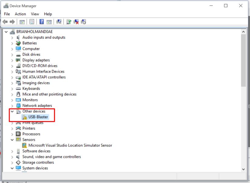
Connect the Altera DE1 USB Cable from the board to your Windows computer with the Altera software installed, flip the RUN/PROG Switch on the DE1 board to the PROG position. Power on the board. Now go to the Windows Device Manager. You should see something similar to the following with the USB-Blaster listed under Other devices:
Right click on the USB-Blaster item and Select Update Driver Software… from the pop-up menu and then select the Browse My Computer for driver software option. Select the following path to locate the USB-Blaster device driver software C:\altera\13.0sp1\quartus\drivers\usb-blaster and choose OK. You should now see the following prompt:
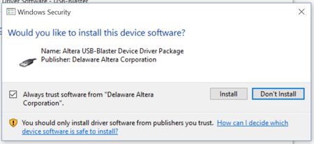
Go ahead and install the driver software and you should get a response that Windows successfully installed the updated driver.
Step 7: Programming the EPROM for Power Cycle Persistence of the Coco3FPGA Firmware
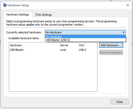
Start the Quartus II software by select the application from Start > Programs > Altera 13.0.1.232 Web Edition > Quartus II 13.0sp1. Start the Programmer feature by choosing the menu item Tools > Programmer. Choose the Hardware Setup button at the top-left of the main programmer window. In the hardware setup window, view the Currently Selected Hardware drop down menu, select USB-Blaster option, then close the hardware setup window.
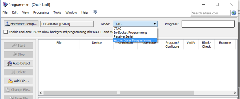
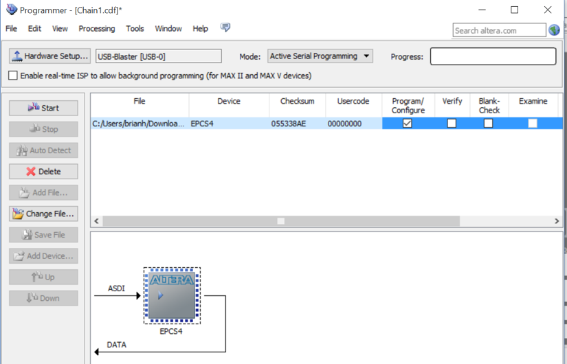
Back in the main programmer window, after the Hardware Setup (which should now say USB-Blaster), there is a Mode selection box where currently JTAG is selected. Change JTAG option to the Active Serial Programming option and the select the Add Files button.
Now go to the directory where you unzipped the Coco3FPGA zip file, browse to the appropriate subfolder depending on whether you have the New SRAM or the old SRAM as explained previously and select the POF file as follows:
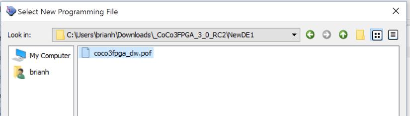
Now you should see a row in a table with the POF file shown. Select the Program/Configure checkbox and click on the Start button.
All of the LED lights should light up on the DE1 board and you should see a progress indicator as follows:
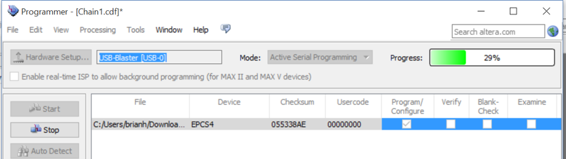
If all goes well, you have now successfully turned a vanilla DE1 board into a Coco3 Plus with 512K RAM. It includes support for DriveWire on the DE1 serial port, Orchestra-90 stereo, VGA output, new video modes including 256 color, and turbo speeds. We have one more step until we are ready to test. Power off the DE1 board one more time.
Step 8: Flashing the Coco3FPGA ROM Image
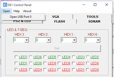
Power the DE1 board back on keeping the RUN/PROG switch in the PROG position. Similar to a normal Coco ROM, we will use the Flash memory on the DE1 to store the modified version of the Coco3 ROM. Go ahead and launch version 1.0.0 of the DE1 Control Panel from Step 3 by running DE1_CD_v0.8\DE1_control_panel\DE1_Control_Panel.exe from your Documents folder or wherever you unzipped it. Now select the Open menu item and select the Open USB Port 0 option.
Go to the Flash tab in the DE1 Control Panel. Select the Chip Erase (40 sec) button to wipe the Flash memory. Enable the File Length checkbox in the Sequential Write section. Next select the Write a File to FLASH button in the same section of the panel. Select the DE1_Flash.bin file you downloaded from the Yahoo Group files section. You should now have a progress indicator show the file being put into Flash.

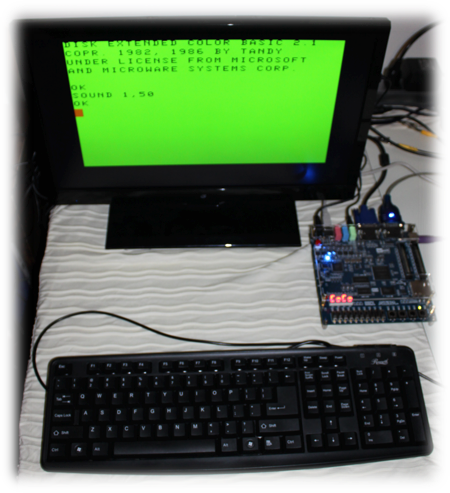
Step 9: Simple System Test
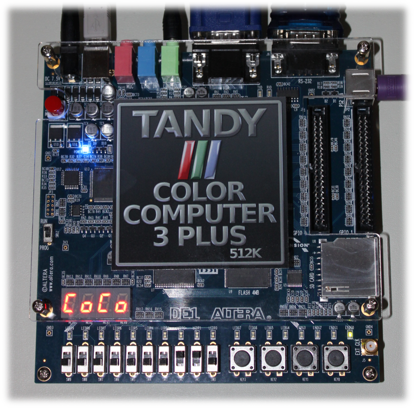
With the flashing of the ROM image, we have completed every step required for you to begin to test your new Coco3. Turn off the DE1 board, change the RUN/PROG switch back to the RUN position and power back on the board. You should now see the familiar green screen and flashing cursor of Disk Extended Color Basic 2.1. You should also see the word CoCo on the segmented display on the DE1 board. Go ahead and type SOUND 1,50 at the basic prompt to test your keyboard and audio.
Congratulations, you now have a 512K Color Computer 3 Plus based on Gary Becker’s Coco3FPGA! Keep in mind that similar to a real Coco3, KEY3 on the DE1 board acts as the reset button.
Step 10: Access Software Through DriveWire
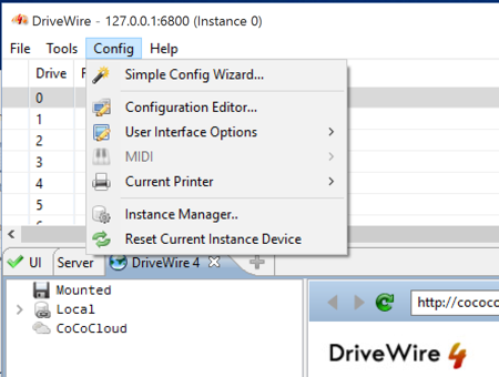
This is not meant to be a tutorial on DriveWire 4 but the DE1 board serial port can support very high baud rates compared to real Coco Machines. If you haven’t installed DriveWire 4, it is a great tool to help you manage your Coco software library and emulate a real floppy drive on the Coco3FPGA. Go ahead and download the zip file from the DriveWire website. You will also need to install the Java download from Oracle as it is a prerequisite for DriveWire. Once installed, from the Tools menu in DriveWire select the Simple Config Wizard.
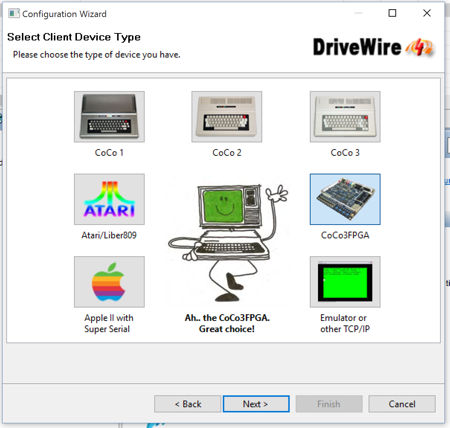
You are asked to select the machine type for DriveWire. You can see there is a specific option for the Coco3FPGA.
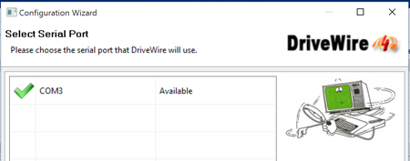
I am using the USB Serial adapter that I referred to in the What You Will Need section. For my setup, it is the only serial device that shows up in the list:
Go ahead and accept all of the default answers in the wizard. The Coco3FPGA default DriveWire baud rate is 115,200. Connect the DB9 end of your USB to Serial adapter to the DE1 board. Gary has a DOS2.DSK file available in the Files area of the Yahoo Group. Go grab that file at this time and put it in Drive 0 in DriveWire. It has some test programs that we will use.
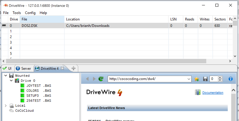
Type DIR at the basic prompt. You should see a directory listing with the files shown above. Go ahead and type RUN “COLORS.BAS”. This is a simple graphic demo that draws some circles and then cycles through various colors. You now have a fully working system with access to the wealth of software available via DriveWire.
Finishing Touches and the Future
Gary has designed an analog board that interfaces into the expansion header on the DE1 board. He also has the schematics up on the Files section of the Yahoo Group. This analog board will have a Coco-compatible joystick port. Obviously, without a joystick port you will only be able to play games that can use the keyboard. You can monitor the Yahoo Group for progress on the analog board. I looked online for proper cases for the DE1 board to no avail. Once we have the size and location of the analog board, some enterprising 3D modeler could create a 3D printed case to give it a traditional fit and finish.
In the mean time, I decided to design a “Tandy Color Computer 3 Plus” logo in the spirit of the Tandy logos of the past using Logoist 2 on my Mac. It is the logo you saw at the beginning of this post. I had a small run of adhesive vinyl stickers printed with this logo on it. It fits perfectly in the center of the clear plastic top protective cover of the DE1 board:
I hope you enjoyed this document and are excited to continue to test the Coco3FPGA project on the Terasic Altera DE1 board. Thanks to Gary Becker for all of his amazing work in the past and his continued work to make this a success!